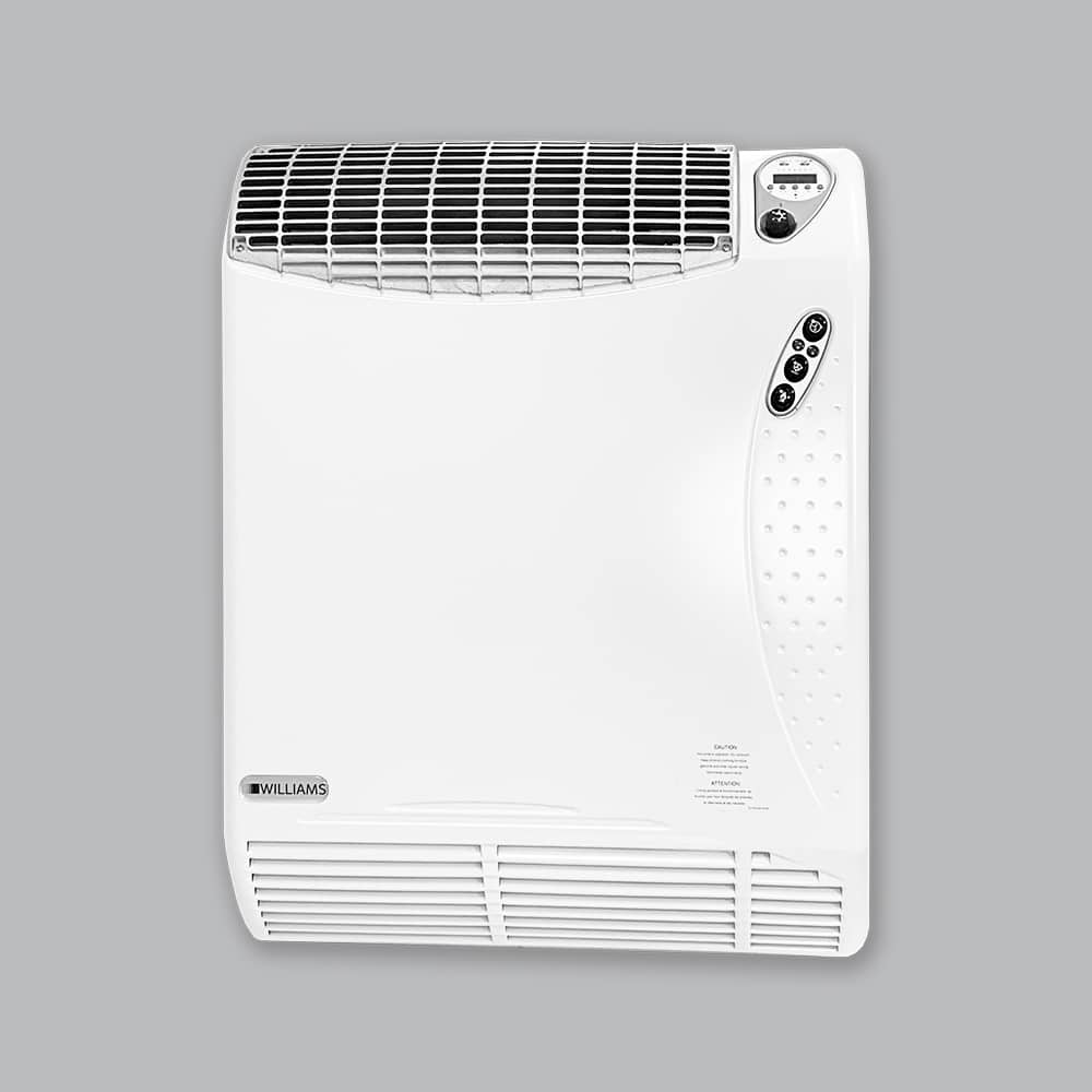
AH Horizontal Deluxe / AV Vertical Deluxe
Williams
AH Horizontal Deluxe / AV Vertical Deluxe
Product Details
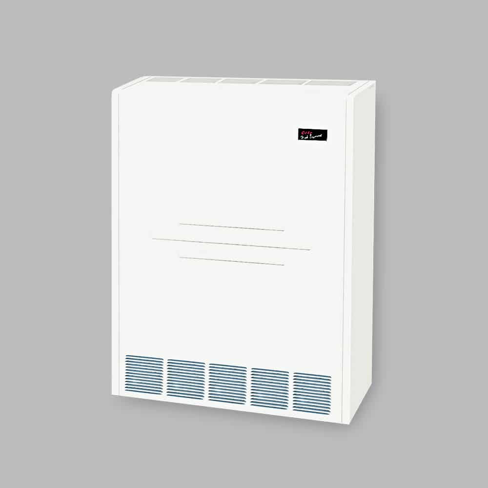
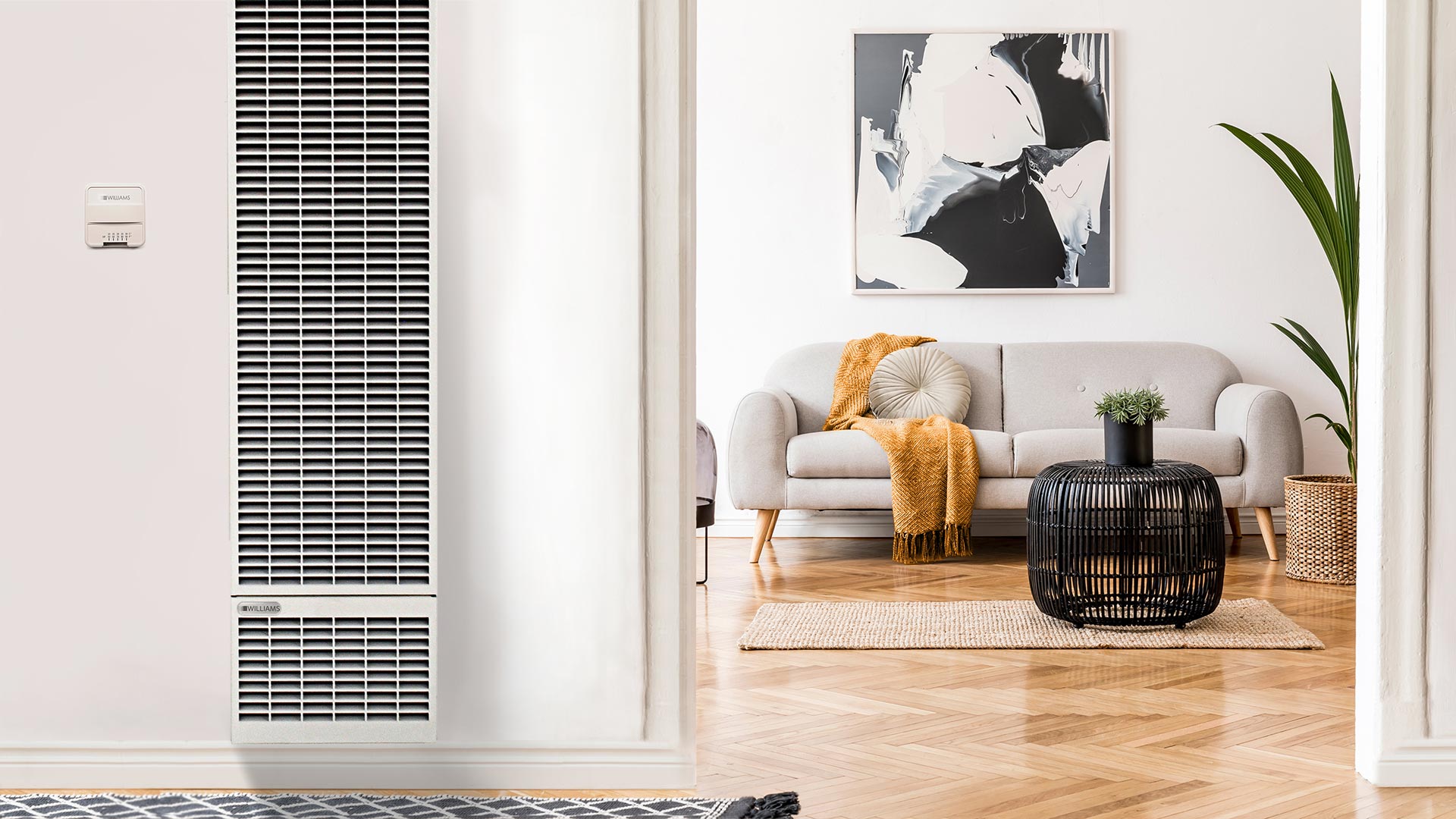
Ideal for applications were a finished cabinet is required, the belt drive (AH/AV-D) is the same unit as our horizontal and vertical basic model, only finished with a baked-on tough, soft white powder coat epoxy and subjected to 1,500 hour salt spray test in accordance with ASTM B117. Access doors are provided on both sides of the unit for easy maintenance. Also available as double-wall (solid or perforated).
CUSTOMIZATIONS
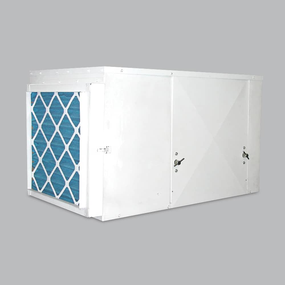
CONSTRUCTION
All unit chassis shall be fabricated of heavy gauge galvanized steel panels able to meet 1,500 hour salt spray test per ASTM B-117. All exterior panels shall be insulated with 1/2″ thick, 1.5 pound per cubic foot, dual density fiberglass insulation rated for a maximum air velocity of 3600 f.p.m. Insulation shall conform to UL 181 for erosion and NFPA 90A and 90B for flame spread (25) and smoke developed (50) rating per ASTM E-84 and UL 723and CAN./ULC, S102-M88.
All concealed units shall have a minimum 1″ duct collar on the discharge.
All exposed units shall have exterior panels fabricated of cold-rolled steel.
Available Options:
- Provide foil faced insulation in lieu of standard. Foil insulation shall meet or exceed the requirements stated above, and in addition, meet ASTM Standards C665 and C-1136 for biological growth in insulation. Insulation shall be lined with aluminum foil, fiberglass scrim reinforcement, and 30 pound kraft paper laminated together with a flame resistant adhesive. All exposed edges shall be sealed to prevent any fibers from reaching the air stream.
- Provide elastomeric closed cell foam Insulation in lieu of standard. Insulation shall conform to UL 181 for erosion and NFPA 90A for fire, smoke and melting, and comply with a 25/50 Flame Spread and Smoke Developed Index per ASTM E-84 or UL
723. Additionally, insulation shall comply with Antimicrobial Performance Rating of zero, no observed growth, per ASTM G21. Polyethylene insulation is not acceptable.
COILS
All cooling and heating coils shall optimize rows and fins per inch to meet the specified capacity. Coils shall have seamless copper tubes and shall be mechanically expanded to provide an efficient, permanent bond between the tube and fin. Fins shall have high efficiency aluminum surface optimized for heat transfer, air pressure drop and carryover.
All coils shall be hydrostatically tested at 350 PSIG air pressure under water, and rated for a maximum of 300 PSIG working pressure at 180°F maximum water temperature. Direct expansion cooling coils shall include a fixed orifice distributor and nozzle.
Steam coils shall be standard steam type suitable for temperatures above 35°F and 15 PSIG maximum working pressure.
Available Options:
- Coil casing shall be fabricated from 304 stainless steel.
- Provide a manual air vent fitting to allow for coil venting.
- Provide a manual-water drain fitting for coil draining.
- Provide automatic air vents in lieu of manual air vents.
- Cooling and heating coils shall be in the common coil casing, heating coils shall be furnished in the re-heat or preheat position on the unit with chilled water coils, and DX coil shall be in preheat position only.
ELECTRIC HEAT
Electric Duct Heaters shall be open coil type. Voltage, KW, size, number of steps and accessories shall be as shown. Units shall be U.L. listed for zero clearance and meet all applicable requirements of the latest National Electric Code and A.N.S.I. standards.
Element temperatures shall not exceed 400ºF below the melting point of the element alloy when energized with design voltage in still, free air at 75ºF ambient. The resistance element is the heart of the heater and should be designed with the operating temperature of the element alloy as the most important criterion. Because no air flow is likely to occur in at least some areas of the heater, this condition will be the basis for design for the entire element.
Frames shall be hot dipped galvanized after fabrication if spot welds are used. Spot welding must be coated after fabrication to prevent corrosion.
Mounting assemblies for the element support insulators shall pass between the insulators permitting free expansion of the insulators under high temperature conditions without cracking or breaking.
The total load of a heater should be divided into steps of no more than 30 amps for good design practice, or less if finer control is required. Units greater than 50 kW shall be controlled by a system with a recycling feature that will not allow all steps to be energized simultaneously.
The recycling feature prevents all steps from being energized simultaneously on power interruptions, cold start, thermostat manipulation, or other abnormal situations. All accessories are furnished as an integral part of each unit. Integrated accessories include air pressure switch, door interlock disconnect switch and transformer.
DRAIN PANS
Primary condensate drain pans shall be single wall, heavy gauge, powder coated epoxy and extend under the entire cooling coil. Drain pans shall be of one piece construction and be positively sloped for condensate removal. Drain pans shall have primary and secondary drain connections.
The drain pan shall be externally insulated with a closed cell foam insulation. The insulation shall carry no more than a 25/50 Flame Spread and Smoke Developed Rating per ASTM E-84 and UL 723 and fungi resistant per ASTM G21/C1338, bacteria resistant per ASTM G22 and mold growth per UL 181.
Available Options:
- Provide a single wall primary drain pan constructed entirely of heavy gauge type 304 stainless steel for superior corrosion resistance. Stainless steel drain pans shall be externally insulated and meet or exceed the requirements stated above.
PIPING PACKAGES
Provide a factory assembled valve piping package to consist of a 2 or 3 way valve body, on/off motorized electric control valve actuator and two isolation ball valves. Control valves are piped normally closed to the coil. Maximum entering water temperature on the control valve is 180°F, and maximum close off pressure is 75 PSIG (1/2″) or 44 PSIG (3/4″). Maximum allowed pressure shall be 300 PSIG.
Available Options:
- Provide 3 wire floating point modulating control valve in lieu of standard 2 position control valve with factory assembled valve piping package.
- Provide either a fixed or adjustable flow control device for each piping package.
- Provide pressure temperature ports for each piping package.
- Strainer for each package. Piping packages are shipped loose on all units and can be installed by request only.
ELECTRICAL
Units shall be furnished with single point power connection. Installer shall provide an electrical junction box with terminal strip for motor and other electrical terminations. Electrical junction box can be ordered separately.
Available Options:
- Electrical junction box with multiple position ¼” spade terminal block to facilitate wiring terminations for the electric control valves
an thermostats. - With Electric Heat, unit may be shipped loose or integrated.
- Include fusing, disconnects, sensors and switches.
FILTERS
All units shall be furnished with a two inch thick, flatly mounted with spring loaded clips on the side access door for easy maintenance without the use of tools.
Available Options:
- Washable filters.